The Hydrological-Thermodynamic Nexus: Sovereign Water Infrastructure, Closed-Loop Industrial Treatment, and the Hidden Bottleneck of Gigawatt Compute & Advanced Fabs
[!NOTE] EDITORIAL & EPISTEMIC CALIBRATION NOTICE This dossier synthesizes empirical thermodynamic mass-energy balances, semiconductor ultrapure water (UPW) specifications (SEMI F63 / ASTM D5127), industrial wastewater engineering benchmarks, and U.S. federal/state environmental regulatory frameworks (EPA Clean Water Act, CERCLA PFAS designations, and UIC Class I/V permitting). Reported commercial deployments and regulatory thresholds are explicitly anchored to primary literature and distinguished from discounted cash flow () impairment scenarios.
"A $10 billion gigawatt AI compute cluster populated with leading-edge GPU racks, or a $20 billion extreme ultraviolet lithography fab, cannot substitute software optimization for the latent heat of vaporization required to reject thermal loads or the ultrapure water required to rinse atomic-scale wafer trenches. In the post-software industrial stack, hydrological sovereignty dictates facility utilization." — Tresslers Group Intelligence, Sovereign Energy Division, Q4 2026
00. Transmission Header#
CLASSIFICATION : Tresslers Group Intelligence // Sovereign Energy & Strategic Infrastructure Divisions
DOMAIN         : Hydrological-Thermodynamic Nexus / Closed-Loop Industrial Treatment / Gigawatt Compute & Sub-2nm Fabs
STATUS         : Active Strategic Intelligence — Sovereign Production Tier (Fact-Checked & Verified Edition)
DATE           : 2026.11.01
LAST_SYNC      : 2026.11.01
AGENTIC_DELTA  : 95% (PINN Predictive Membrane Autonomy & AP2/x402 M2M Hydrological Settlement)
TPM_V1         : Conviction 9.8 // Strategic Impact 9.9 // Maturity 8.7 // Geopolitical Risk 9.1
ALERT LEVEL    : Tier-1 Physical Bottleneck — Coupled Megawatt-Molecule O-Ring Constraint
ONTOLOGY NODE  : Hydrological-Thermodynamic Sovereign Matrix (TREG-HTSN-2026)
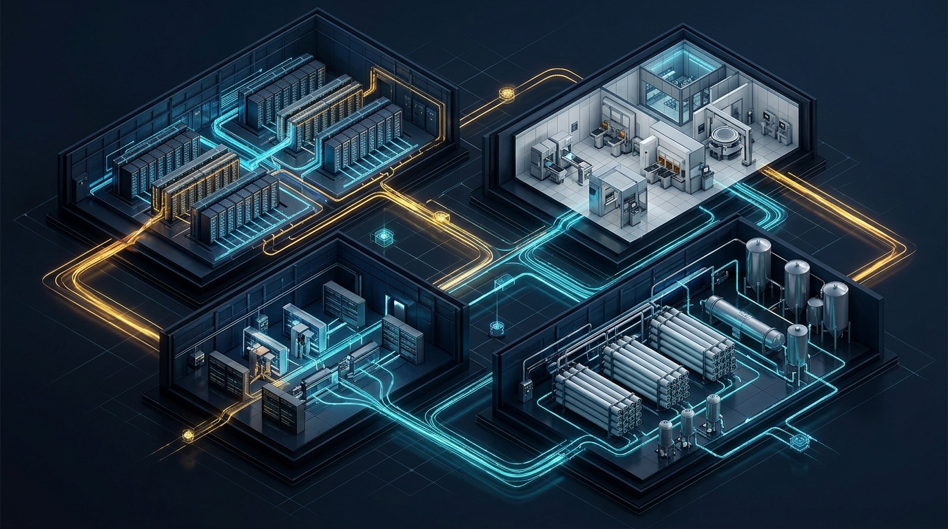
I. The Macroeconomic & Thermodynamic Thesis (Post-Software Rent Migration)#
Conservation of Attractive Profits in Physical Bottlenecks#
The global technology sector is undergoing a structural regime shift from marginal-cost-zero software replication to capital-intensive, thermodynamically bounded industrial production. Under Clayton Christensen’s Law of Conservation of Attractive Profits, whenever a previously proprietary, integrated layer of a value chain becomes modularized and commoditized, the ability to earn abnormal economic rents migrates to an adjacent layer that remains proprietary, non-substitutable, and physically constrained. Over the past decade, foundation model weights, statistical inference pipelines, and standard semiconductor design blocks have experienced rapid horizontal commoditization. As algorithmic efficiency converges across frontier laboratories and fabless silicon designers compete for identical foundry allocations, economic rent is migrating downward into the physical substrate: delivered firm megawatts () and high-purity water molecules ().
This rent migration is governed mathematically by Michael Kremer’s O-Ring Production Function, in which a complex, high-value output depends on the multiplicative execution of critical, non-substitutable subtasks:
In this formulation, represents realized economic output (such as completed frontier AI training runs or yielded sub- logic wafers), represents deployed physical capital, is output per task under optimal conditions, and represents the reliability or availability probability of critical input . Unlike additive Cobb-Douglas production functions—where a scarcity in one factor can be compensated by substituting another—the O-Ring function dictates that if any single physical utility bottleneck or approaches zero, the marginal productivity of all other deployed capital () collapses toward zero. A $10 billion gigawatt AI compute cluster populated with leading-edge GPU racks, or a $20 billion extreme ultraviolet (EUV) lithography fab, cannot substitute software optimization for the latent heat of vaporization required to reject thermal loads or the ultrapure water (UPW) required to rinse atomic-scale wafer trenches. Consequently, sovereign and private entities that control assured, drought-proof hydrological rights, high-recovery closed-loop treatment trains, and thermal rejection permits capture disproportionate economic value, dictating facility utilization rates and asset valuations across the digital-industrial stack.
Interactive Telemetry Module 01: Use the O-Ring Production Simulator below to model how physical utility bottlenecks () multiplicatively constrain realized return on capital across gigawatt compute and semiconductor fabrication assets.
The Coupled Energy-Water Tradeoff Curve#
At the facility boundary, data center and fab operators confront a rigid thermodynamic Pareto frontier coupling Power Usage Effectiveness () and Water Usage Effectiveness (). Defined by The Green Grid, these metrics express the ratio of total facility energy and site water consumption to actual IT equipment energy:
Conventional hyperscale facilities rely on open-loop evaporative cooling towers or adiabatic fluid coolers because water possesses an extraordinarily high latent heat of vaporization ( at ) compared to the sensible heat capacity of ambient air (). Evaporating of water absorbs roughly the same thermal energy as raising of dry air by . Consequently, evaporative architectures achieve highly competitive values of , but incur direct on-site consumptive water losses yielding an industry-average .
When municipal water curtailments or public opposition force operators to abandon evaporative rejection in favor of dry, air-cooled magnetic-bearing centrifugal chillers, the facility eliminates direct on-site evaporation (). However, this shift forces the refrigeration cycle to reject heat against the ambient dry-bulb temperature () rather than the significantly lower ambient wet-bulb temperature (). In arid or subtropical summer conditions where reaches () while remains at , the condensing pressure and temperature () of the chiller refrigerant must rise above to maintain a viable heat transfer approach temperature (). By the Carnot efficiency limit of a vapor-compression cycle, the Coefficient of Performance () degrades sharply as the temperature lift () widens:
Even utilizing frictionless magnetic-bearing compressors with variable-frequency drives (), increasing condensing temperatures by during peak ambient dry-bulb hours collapses chiller from (water-cooled) down to (air-cooled), while simultaneously requiring massive axial fan arrays to move low-density air across fin-tube condensers. This imposes a parasitic electrical kilowatt penalty ( jumping from to ) precisely during peak summer grid stress.
Crucially, eliminating via dry cooling frequently fails to reduce total watershed depletion when accounting for Scope 2 (indirect grid) water consumption, encapsulated in the source-inclusive metric :
Here, is the Electricity Water Intensity Factor ( sent out) of the regional balancing authority. Thermoelectric baseload generators (combined-cycle gas turbines, coal, and nuclear units) utilizing wet cooling towers or once-through condensers consume between and of electricity sent out. If a gigawatt data center switches from evaporative cooling (, ) to dry chillers (, ) on a grid where marginal peak generation carries an of , the facility incurs an additional of grid electricity per of IT load, evaporating upstream at the power station while permanently consuming more scarce grid transformer and transmission capacity. Thus, uncoupled dry cooling merely exports entropy and hydrological stress from the data center fence line to the regional thermoelectric grid.
The Co-Location Paradox#
The macroeconomic vulnerability of the AI and semiconductor buildout is compounded by a severe geographic collision: the very regions selected for cheap land, subsidized industrial policy (such as U.S. CHIPS Act corridors), fiber optic convergence, or abundant natural gas and solar generation overlap directly with the world's most over-allocated, drought-stressed hydrological basins.
In the ERCOT, Permian Basin, and Edwards-Trinity Aquifer corridor of Texas, West and Central Texas host the fastest-growing pipeline of AI training campuses, attracted by behind-the-meter Permian natural gas, high wind and solar penetration, and rapid interconnection queues, alongside expanding semiconductor fabs in Austin, Taylor, and Sherman. However, the Permian Basin and Edwards-Trinity plateau face acute groundwater depletion coupled with extreme subsurface disposal constraints. While the oil and gas sector generates of hypersaline produced water annually across the United States, shallow aquifers are rapidly salinizing, and surface reservoirs along the Colorado and Brazos rivers enforce strict drought-contingency curtailments on junior industrial permittees.
A similar collision defines the Phoenix Active Management Area (AMA) and Gila River Basin in Arizona. The Greater Phoenix corridor—spanning Chandler, Ocotillo, North Phoenix, Goodyear, and Mesa—anchors over $150 billion in leading-edge logic fab investments alongside massive hyperscale data center clusters. This industrial concentration sits within a desert basin subject to Colorado River Tier 1 and Tier 2 shortage declarations on the Central Arizona Project (CAP) canal and stringent 100-year Assured Water Supply (AWS) groundwater moratoria under the Arizona Department of Water Resources (ADWR). Municipal utilities have increasingly restricted new evaporative cooling connections exceeding , forcing industrial entrants to fund multi-hundred-million-dollar water reclamation plants or zero-water cooling retrofits.
In the Eastern United States, the Northern Virginia Potomac Watershed across Loudoun, Prince William, and Fairfax Counties serves as the global interconnection hub with over of operational and planned data center capacity, relying heavily on the Potomac River basin and Occoquan Reservoir. While historically viewed as a water-abundant eastern riparian region, low-flow late-summer conditions in the Potomac—managed by the Interstate Commission on the Potomac River Basin (ICPRB)—create acute seasonal pinch points where simultaneous municipal drinking water withdrawals and multi-gigawatt evaporative cooling spikes threaten minimum environmental instream flows.
In East Asia, Taiwan’s Hsinchu, Taichung, and Tainan Science Parks represent the global epicenter of sub- and sub- logic foundry manufacturing, operating on a mountainous island where steep topography sends over of annual rainfall directly to the ocean unless captured by silt-prone reservoirs. During periodic plum-rain and typhoon failures, reservoir storage in Baoshan and Zengwen drops below , forcing the Taiwanese government to fallow tens of thousands of hectares of irrigated rice paddies, deploy mobile container reverse osmosis desalination units, and mandate that foundries achieve process water reclamation and utilize reclaimed municipal effluent.
Stranded Capital Risk & Valuation Discounts#
When hydrological and environmental permitting realities collide with gigawatt-scale capital deployment, the financial consequences manifest as severe Net Present Value () destruction and asset impairment. Consider a baseline discounted cash flow () valuation for a AI Compute Campus requiring $10.0 billion in upfront CapEx ($10M/MW inclusive of powered shell, electrical switchgear, cooling plant, and accelerated compute racks), modeled over a 10-year economic life at a weighted average cost of capital () and generating $2.50 billion in baseline annual net operating cash flows:
When a facility encounters hydrological shocks—such as municipal allocation curtailments, National Pollutant Discharge Elimination System (NPDES) thermal or salinity discharge denials, or drought-tier moratoria halting Phase 2 expansions—capital impairment follows three distinct trajectories. Under Scenario A (Municipal Water Curtailment / Thermal De-Rating), a drought declaration or municipal supply shortfall in Year 2 imposes a curtailment on cooling makeup water allocation. Without sufficient evaporative heat rejection, the cluster must throttle GPU clock speeds or idle of its rack capacity, reducing annual net cash flows from $2.50B to $1.625B for Years 2 through 10. The present value of cash flows plunges from $15.36B to $10.78 billion, representing a $4.58 billion valuation impairment ( of ) and wiping out of the project's net economic value as falls to $0.78B.
Under Scenario B (Emergency Dry-Chiller & ZLD Retrofit), faced with an NPDES blowdown discharge denial or allocation cut in Year 2, the operator executes an emergency $350 million CapEx retrofit to install closed-loop dry chillers and a Zero Liquid Discharge (ZLD) brine concentrator. While avoiding total shutdown, the parasitic electrical penalty of dry cooling and thermal ZLD consumes of annual facility power capacity, reducing sellable compute throughput and raising operating expenses. Present value drops to $13.50 billion, inflicting a $1.86 billion valuation impairment ( of ).
Under Scenario C (Drought-Tier Moratorium / Phase-2 Expansion Delay), a campus or $20B+ semiconductor fab deploys Phase 1 ( capacity), but local water regulators impose a 24-month moratorium on Phase 2 utility hookups or wastewater discharge permits, delaying full ramp from Year 2 to Year 4. For the $10B compute campus, present value falls to $12.25 billion, resulting in a $3.11 billion impairment ( of ). Applied proportionally to a $20 billion leading-edge logic fab, where tool depreciation on EUV scanners costing $180M–$380M each occurs on a rigid node-obsolescence clock, a two-year hydrological delay destroys $6.2 billion in present value, rendering the node uncompetitive before reaching high-volume manufacturing.
II. Gigawatt Compute & Thermal Rejection Architectures#
1 GW IT Load Mass & Energy Balance#
The transition from legacy air-cooled cloud servers ( per rack) to ultra-dense accelerated AI architectures—such as NVIDIA Blackwell (GB200/GB300 NVL72 at per rack) and Rubin-class architectures ( per rack)—fundamentally alters the enthalpy and mass-flow balances of a gigawatt-scale compute campus. Because of electrical work consumed by complementary metal-oxide-semiconductor (CMOS) transistors is ultimately dissipated as thermal energy via Joule heating, a () IT cluster requires continuous steady-state thermal rejection of (excluding auxiliary facility loads).
In a Direct-to-Chip (DTC) single-phase liquid cooling loop, heat is extracted from GPU and CPU cold plates into a circulating coolant loop before being transferred via liquid-to-liquid Coolant Distribution Units (CDUs) to the primary facility cooling water loop. The required mass flow rate () across the facility loop is governed by the sensible heat balance:
Assuming pure water () operating across a standard temperature differential (e.g., supply to return), a cluster requires a primary circulating mass flow rate of , equivalent to . If the loop operates at a tighter ( to ), the circulating flow requirement escalates to (). If a propylene glycol/water (PGW) mixture () is utilized in the secondary loop at , volumetric flow exceeds , requiring massive main headers and multi-megawatt variable-speed pumping stations.
When this thermal load is rejected to the atmosphere via open-loop evaporative cooling towers, the theoretical minimum pure evaporation rate () is dictated by the latent heat of vaporization at the cooling tower sump temperature ( at ):
Thus, pure latent evaporation for the IT load alone consumes or . However, cooling towers cannot evaporate of incoming feedwater without precipitating dissolved minerals onto heat exchanger surfaces. Operators must continuously purge a fraction of the concentrated sump water—termed blowdown ()—to maintain dissolved ions below saturation limits. Defining the Cycles of Concentration () as the ratio of chloride or conductivity in the circulating blowdown water () to that of the raw makeup water (), and neglecting windage drift ( of circulating flow), the steady-state mass and solute conservation equations yield:
When accounting for auxiliary facility heat loads (, including switchgear, UPS losses, chillers, and pumps), peak summer ambient psychrometrics, and hard-water blowdown constraints (), gross facility makeup water demand scales from the theoretical (at , IT load only) up to ( for a campus). The stoichiometric mass balance across regimes from to for the pure IT thermal load is detailed below:
| Cycles of Concentration (CoC) | Pure Evaporation Rate (GPD) | Blowdown Purge Volume (GPD) | Blowdown Purge Volume (MGD) | Gross Makeup Water Demand (GPD) | Gross Makeup Demand (MGD) | Specific Makeup Intensity (GPD/MW) | Site WUE (L/kWh) |
|---|---|---|---|---|---|---|---|
As the stoichiometric data indicates, increasing from to saves of makeup water ( down to ) and cuts blowdown wastewater volume by ( down to ), whereas pushing from to yields diminishing returns (only saved) while exponentially elevating mineral scaling risks.
Direct-to-Chip (DTC) Warm-Water Loops vs. Immersion#
Within the white space of a rack cluster, thermal capture occurs via two competing liquid architectures: Direct-to-Chip (DTC) cold plates using warm treated water or propylene glycol/water (), or Single-/Two-Phase Immersion Cooling using synthetic dielectric hydrocarbons, esters, or fluorochemicals.
In DTC warm-water architectures (standardized under ASHRAE W4/W45 guidelines with supply temperatures and return temperatures), the coolant flows through copper microchannel cold plates featuring fin pitches of mounted directly onto GPU dies. While water’s superior thermal conductivity () and low viscosity ( at ) outperform dielectric immersion fluids by in convective heat transfer coefficient, operating warm aqueous loops inside multi-metal assemblies (C11000 copper cold plates, 316L stainless steel manifolds, EPDM/FKM elastomers, and brazed nickel/silver joints) triggers severe corrosion and fouling kinetics.
First, galvanic and cuprosolvency kinetics accelerate rapidly with temperature. At , the Arrhenius reaction rate of copper oxidation increases by relative to chilled water (). If dissolved oxygen () exceeds , oxidizes to cuprous oxide () and cupric oxide (), which dissolves as ions at high velocity and re-deposits onto lower-potential stainless steel or aluminum surfaces, triggering localized pitting corrosion. Consequently, high-reliability DTC loops enforce strict deoxygenation () using membrane degasifiers or nitrogen-blanketed expansion tanks, paired with azole passivation chemistry (benzotriazole [BZT] or tolyltriazole [TTA] maintained at , or next-generation carboxylates) that chemisorb onto copper surfaces to form a hydrophobic polymeric barrier.
Second, glycol degradation and biological fouling threaten loop chemistry over time. In loops, thermal-oxidative degradation of propylene glycol in the presence of dissolved oxygen and copper catalysis produces organic acids (lactic, acetic, pyruvic, and formic acids). Left unchecked, these organic acids depress loop below , stripping the passive oxide film from copper and stainless steel. Simultaneously, diluted PGW () at serves as an ideal nutrient substrate for Pseudomonas, sulfate-reducing bacteria (SRB), and iron-oxidizing bacteria, creating extracellular polymeric substance (EPS) biofilms that bridge microchannels and cause catastrophic localized GPU thermal throttling.
Third, sub-micron particulate filtration is mandatory to protect microchannel geometries. Because microchannel cold plates act as mechanical strainers across thousands of parallel GPU packages, standard strainer baskets are wholly inadequate. Modern gigawatt CDU skids require continuous side-stream and inline sub-micron to absolute pleated filtration (often pairing main-loop filters with side-stream polishing and mixed-bed ion-exchange cartridges) to strip colloidal metal oxides and elastomer leachates.
By contrast, Single-Phase Immersion Cooling submerges entire server blades in synthetic polyalphaolefins (PAO) or gas-to-liquid (GTL) isoparaffinic hydrocarbons, eliminating internal microchannel clogging, galvanic corrosion, and server fan power ( heat capture vs. for DTC). However, dielectric hydrocarbons exhibit higher kinematic viscosity and only one-third the volumetric heat capacity of water, requiring larger heat exchangers, heavier floor loading, and vertical tank form factors. Two-Phase Immersion Cooling, which boils fluoroketones or hydrofluoroethers (HFEs) at on GPU vapor chambers, faces severe regulatory and supply-chain existential risk due to Per- and Polyfluoroalkyl Substances (PFAS) phase-outs, high fluid cost ($150–$300/L), and fugitive vapor loss during maintenance. Thus, DTC warm-water loops coupled with rear-door heat exchangers remain the dominant architecture for Blackwell and Rubin deployments.
Waste-Heat Driven Desalination & Thermal Arbitrage#
The structural advantage of DTC warm-water cooling—capturing IT heat in a dense liquid medium at rather than dispersing it into low-enthalpy air—unlocks a profound thermodynamic arbitrage: using data center waste heat to drive Forward Osmosis (FO) or Multi-Effect Distillation (MED) desalination on impaired brackish groundwater, seawater, or oilfield produced water.
In October 2026, data center infrastructure developer Endeavour (owner of Edged Energy and ThermalWorks) and desalination firm Trevi Systems announced a commercial deployment architecture pairing Endeavour’s ThermalWorks closed-loop waterless cooling platform directly with Trevi’s thermally regenerated Forward Osmosis system. Unlike Reverse Osmosis (RO), which relies on electrically driven high-pressure pumps () to force water across a semi-permeable membrane against osmotic pressure, Trevi’s FO process uses a proprietary, food-grade retrograde thermolytic solute draw solution (AquaDraw™) with an osmotic pressure exceeding that of hypersaline brines.
The thermodynamic cycle operates across four continuous stages. During initial osmotic extraction at low hydraulic pressure, impaired feedwater (brackish groundwater, municipal RO reject brine, or produced water) flows along one side of a semi-permeable FO membrane while the concentrated thermolytic draw solution flows counter-currently on the permeate side. Pure water naturally diffuses across the membrane into the draw solution via osmotic potential (), leaving salts, heavy metals, and particulates behind in a highly concentrated brine. Next, the diluted draw solution undergoes retrograde phase separation via data center waste heat, passing through liquid-to-liquid heat exchangers (ThermoSnare™) fed by waste heat captured directly from the data center IT cooling loop. Because the draw solute exhibits retrograde (inverse) solubility, heating it to a precise threshold between and triggers an abrupt liquid-liquid phase separation—analogous to oil separating from water—without requiring the latent heat of vaporization needed to boil water in conventional thermal evaporators. During solute recycling and recuperation, the separated, concentrated draw solute phase is decanted through regenerative heat exchangers (recuperating the majority of sensible thermal energy) and recycled back to the FO membrane module in a closed loop. Finally, the low-salinity aqueous phase passes through a low-pressure polishing nanofilter to meet World Health Organization (WHO) and NSF drinking water standards, while the concentrated feed brine is routed to heat-driven crystallizers (SaltVault™) that reduce purchased electrical energy for brine crystallization by compared to conventional electric Mechanical Vapor Recompression (MVR).
Because phase separation of the retrograde thermolytic draw solute requires only sensible heating across a narrow with high internal heat recuperation ( lower electrical energy than RO), the specific water yield per unit of compute thermal energy flips the facility's hydrological polarity. On brackish groundwater feed, the coupled system generates up to () of clean freshwater per of computing capacity, corresponding to a net water production rate of of computing. On hypersaline oilfield produced water feed, the system yields up to . Evaluated at the scale of a AI campus, whereas a conventional evaporative cooling architecture at consumes of water () and a standalone ThermalWorks closed-loop waterless system operates at a neutral (), pairing the campus with waste-heat FO desalination turns the facility into a net water producer on oilfield produced water or a water production plant on brackish groundwater whose thermal energy is already paid for by the adjacent computing load. Scaled to a cluster, the facility transitions from an net water consumer into a net freshwater generator.
Cooling Tower Blowdown Chemistry & Scaling Limits#
For facilities that continue operating evaporative cooling towers, the maximum achievable Cycles of Concentration () is strictly governed by mineral precipitation and corrosion boundaries in the recirculating water.
The most rigid ceiling in western and volcanic basins is amorphous silica polymerization (). Unlike carbonate salts, dissolved reactive silica () polymerizes at neutral-to-slightly-acidic to form glassy, amorphous colloidal silica scale () on condenser tubes. Once deposited, silica scale has an extremely low thermal conductivity () and cannot be dissolved by standard hydrochloric or citric acid cleanings, requiring hazardous hydrofluoric acid () or ammonium bifluoride. In open cooling towers without specialized dendrimer or copolymer dispersants, recirculating must be strictly capped at (or up to with advanced silica-inhibiting polymers or at elevated where silica ionizes to soluble silicate , provided magnesium is low to prevent lethal magnesium silicate [] precipitation). Consequently, in volcanic or desert groundwater basins such as Arizona or Central Texas, where raw makeup water contains of , silica alone caps at unless lime-soda or magnesium-oxide side-stream softening is installed.
A second universal boundary is calcium carbonate () scaling, governed by the Langelier Saturation Index (). Calcium carbonate exhibits retrograde solubility, meaning its solubility product () decreases as water temperature increases across the heat exchanger surface. The scaling propensity is quantified by the Langelier Saturation Index ():
where is the measured bulk water , is the at saturation, adjusts for ionic strength, adjusts for temperature, , and . When , water is undersaturated and corrosive to steel and copper; when , water is supersaturated and scale-forming. Without scale inhibitors, cooling towers must maintain . By dosing phosphonate antiscalants (such as HEDP [1-hydroxyethylidene-1,1-diphosphonic acid] or PBTC [2-phosphonobutane-1,2,4-tricarboxylic acid] at ) combined with sulfonated polycarboxylate dispersants, operators can stabilize supersaturated water up to (Ryznar Stability Index ). Pushing beyond requires continuous sulfuric acid () dosing to convert bicarbonate alkalinity () into dissolved gas stripped in the tower fill:
While sulfuric acid dosing eliminates carbonate alkalinity, it adds sulfate ions () to the recirculating loop, introducing calcium sulfate (gypsum) and calcium phosphate limits. To prevent gypsum () precipitation, the ionic product of calcium and sulfate (expressed in as or ion concentrations) must remain below the inhibited threshold:
Similarly, when reclaimed municipal secondary effluent is used as cooling tower makeup, orthophosphate () concentrations of react with high calcium at to precipitate tricalcium phosphate (, ), requiring specialized terpolymer dispersants once circulating exceeds .
III. Advanced Semiconductor Fabs & Ultrapure Water (UPW) Synthesis#
Volumetric & Purity Scaling at Sub-2nm Nodes#
While gigawatt AI data centers utilize water primarily as a bulk thermodynamic heat-transfer fluid, leading-edge semiconductor fabrication plants (fabs) operating at sub- (, , and ) Gate-All-Around (GAA) nanosheet and Backside Power Delivery Network (BSPDN) nodes utilize water as an atomic-precision chemical solvent and mechanical rinsing agent. A single high-volume leading-edge logic or DRAM mega-fab complex requires of raw municipal or industrial feedwater.
As transistor architectures transition from FinFET to vertically stacked GAA nanosheets and High-Numerical-Aperture (High-NA) EUV lithography, the number of distinct wafer mask layers, wet chemical etches, atomic layer depositions (ALD), and chemical mechanical planarization (CMP) steps exceeds passes per wafer. Between every single chemical bath—including hydrofluoric acid oxide strips, sulfuric-peroxide ("piranha") resist strips, SC-1/SC-2 RCA cleans, and electroplating steps—the silicon wafer must be rinsed thoroughly with Ultrapure Water (UPW). At a pitch, the critical killer defect size is defined by the International Roadmap for Devices and Systems (IRDS) as roughly half the minimum feature half-pitch—meaning a single metallic ion, organic oligomer, or silica nanoparticle measuring bridged across two nanosheet channels causes a catastrophic electrical short or threshold voltage shift, destroying a wafer worth $20,000 to $40,000.
Because the multi-stage membrane, ion-exchange, and ultrafiltration synthesis train generates reject brines and backwash streams at every purification step, producing of semiconductor-grade UPW requires of raw input feedwater (an overall UPW synthesis yield of prior to secondary brine recovery). Consequently, a raw water intake yields approximately of UPW directed to the cleanroom tools, while generating of UPW reject that must be blended with cooling tower makeup or routed to industrial wastewater reclamation.
ASTM Type E-1 / SEMI F63 Specifications#
Semiconductor UPW quality is governed globally by SEMI F63 (Guide for Ultrapure Water Used in Semiconductor Processing, updated biennially to align with IRDS node shrinkage) and ASTM D5127 (Standard Guide for Ultra-Pure Water Used in the Electronics and Semiconductor Industry, classes Type E-1 through E-4, with Type E-1.3 representing advanced sub- extensions). Furthermore, piping and distribution materials are strictly constrained under SEMI F57, which mandates high-purity polyvinylidene fluoride (PVDF) or perfluoroalkoxy alkane (PFA) fluoropolymers to prevent trace metal or organic leaching.
At , completely pure water undergoes self-ionization () with an ionic product . Given the limiting molar conductivities of () and (), the theoretical minimum electrical conductivity of pure water at is , which corresponds to a theoretical maximum resistivity of . Sub- UPW systems must operate continuously at , meaning total conductive ion impurities are suppressed to the parts-per-trillion (, ) regime.
| Parameter | Units | ASTM D5127 Type E-1 Baseline | SEMI F63 / Sub-2nm Advanced Spec (Type E-1.3) | Primary Defect Mechanism on Sub-2nm Wafer |
|---|---|---|---|---|
| Resistivity at | Ionic contamination; gate oxide breakdown & leakage current | |||
| Total Organic Carbon (TOC) | () | Carbonaceous residue ("haze") during EUV/ArF lithography & epi growth | ||
| Dissolved Reactive Silica () | () | Uncontrolled silicon oxide islands; epitaxial stacking faults | ||
| Dissolved Oxygen (DO) | () | Uncontrolled native oxide () growth on bare / cracking | ||
| Critical Particles () | () | Physical bridging across GAA nanosheets & High-NA EUV interconnects | ||
| Viable Bacteria | Biofilm sloughing; localized organic and metallic focal defects | |||
| Boron () | () | Unintended p-type dopant diffusion altering transistor threshold voltage () | ||
| Trace Metals () | () | each | each | Mid-gap recombination traps; mobile ion drift in high- gate dielectrics |
Achieving this specification requires a three-subsystem, multi-stage synthesis train integrated into the fab’s SCADA loop via real-time inline analyzers. In the initial pretreatment subsystem, raw municipal feedwater undergoes inline coagulation, multimedia or ceramic ultrafiltration (removing suspended solids down to and reducing Silt Density Index ), activated carbon or bisulfite dechlorination, and antiscalant/pH conditioning. The water then enters a two-pass Reverse Osmosis (RO) array, where first-pass brackish water RO membranes operate at , rejecting of divalent ions and of monovalent ions. Caustic () is dosed between Pass 1 and Pass 2 to raise to , converting dissolved carbon dioxide () into bicarbonate () and weakly ionized boric acid (, ) and silicic acid (, ) into charged ions that are rejected by the second-pass high-purity RO membranes.
Following two-pass RO, the permeate enters vacuum membrane degasification (MDG), where hydrophobic microporous polypropylene or polymethylpentene hollow-fiber membrane contactors apply a deep vacuum combined with high-purity nitrogen () sweep gas on the shell side, stripping dissolved oxygen () down to and removing residual to protect downstream ion-exchange capacity and prevent silicon carbide () or silicon epitaxial reactor oxidation. Next, UV photo-oxidation reactors utilize low-pressure, high-intensity mercury vapor UV lamps emitting at to cleave water molecules via homolytic photolysis () and generate hydroxyl radicals (, ). These radicals mineralize neutral, low-molecular-weight trace organics (such as urea, methanol, and isopropyl alcohol [IPA] that slip through RO membranes) into charged carbonate ions () and carboxylic acids, reducing below .
In the subsequent make-up and polishing loops, continuous Electrodeionization (EDI) stacks pack high-purity styrene-divinylbenzene cation and anion exchange resins between ion-selective membranes under a direct-current electric field. The electric field continuously splits water at the resin interfaces into and ions, regenerating the resin beds in situ without chemical acid or caustic downtime. Advanced EDI modules achieve boron and silica removal and sodium and chloride removal, hitting boron without separate boron-selective chelating resins, followed by nuclear-grade sacrificial mixed-bed polishing columns to lock resistivity at . Just prior to the wafer wet benches, bactericidal UV sterilizes any trace microbial DNA, and polysulfone or PTFE hollow-fiber Point-of-Use Ultrafiltration (POU-UF) modules (molecular weight cut-off , pore size ) strip any sheared resin fragments or colloidal particles down to at .
The Three Hard Fab Effluent Streams#
To comply with stringent municipal discharge limits and achieve the internal water reclamation rates mandated in water-stressed basins like Taiwan and Arizona, semiconductor fabs cannot mix their drain lines into a single equalization basin. Instead, modern fabs deploy point-of-tool source segregation across up to distinct drain networks, dominated by three notoriously refractory process streams.
Chemical Mechanical Planarization (CMP) Slurries
CMP is used repeatedly at sub- nodes to planarize dielectric oxides (), tungsten () plugs, cobalt/ruthenium barrier layers, and copper () interconnects. CMP wastewater contains high concentrations of engineered nanoparticles ( colloidal silica [], cerium oxide [], or alumina []) suspended at high zeta potential (), alongside hydrogen peroxide (), corrosion inhibitors (BZT), chelating agents (citric acid, ethylenediamine, glycine), and non-ionic/anionic surfactants. Because CMP nanoparticles are sterically and electrostatically stabilized by surfactants to prevent agglomeration during wafer polishing, they fiercely resist gravitational settling in conventional lamella clarifiers. Furthermore, during fab shift changes or tool recipe transitions, surfactant and solids spikes cause clarifier carry-over that irreversibly fouls downstream polymeric polyvinylidene fluoride (PVDF) or polyethersulfone (PES) ultrafiltration membranes via hydrophobic surfactant adsorption and abrasive lumen scouring.
To overcome polymeric membrane failure, leading Taiwanese and U.S. foundries have increasingly replaced sprawling coagulation-flocculation-lamella clarifier trains with inline coagulation and adjustment followed directly by pressurized Ceramic Ultrafiltration (CUF) monoliths—such as Acuriant’s Nanostone CUF|Shield™ (CM-151) and CUF|ShieldPlus™ (CM-151 ME, deployed across more than semiconductor sites globally) or silicon carbide () dead-end monoliths. Operating in dead-end mode rather than high-recirculation crossflow cuts pumping specific energy consumption by up to compared to crossflow tubular ceramics, while reducing system physical footprint by over . Because the sintered ceramic matrix (pore size ) is hydrophilic and chemically inert across , it tolerates feed turbidities up to , resists abrasive silica and ceria nanoparticles without fiber breakage, extends clean-in-place (CIP) intervals to over three months, and achieves water recovery with RO-ready permeate (), saving roughly $800,000 annually per skid in chemical, sludge, and freshwater costs.
Backgrind, Dicing & Cutting Streams
Before 3D-IC and CoWoS advanced packaging, silicon wafers are mechanically thinned (background) from down to using diamond grinding wheels lubricated by high-purity water and organic cutting coolants, followed by laser or blade dicing. Backgrind effluent carries high loadings of angular, sub-micron elemental silicon () shards () coated in organic coolants and surfactants. When routed to polymeric hollow-fiber UF membranes, the sharp silicon shards abrade the polymer skin layer and pin inside membrane pores during backwash, while organic coolants blind the hydrophobic PVDF surface. Using ceramic monoliths (CUF|Shield™), backgrind and cutting wastewater undergoes direct dead-end filtration without chemical coagulant pretreatment. High-pressure hydraulic backwashes dislodge the incompressible silicon filter cake cleanly, elevating recovery from (in legacy clarifier and polymeric systems) to over and returning permeate directly to the UPW make-up train.
Hydrofluoric Acid (HF), Tetramethylammonium Hydroxide (TMAH), and Heavy Metal Streams
Wet etching and photoresist development generate highly toxic chemical effluents that severely inhibit biological wastewater plants and contaminate downstream RO membranes if not destroyed or crystallized at the source. Concentrated and dilute hydrofluoric acid () drains contain of fluoride () alongside fluorosilicic acid (). While legacy fabs used two-stage lime () and polyaluminum chloride (PAC) precipitation—producing massive volumes of hazardous, high-moisture ( water) calcium fluoride () sludge while leaving residual —modern fabs deploy fluidized-bed crystallization reactors seeded with high-purity silica sand or synthetic pellets paired with ceramic UF polishing:
The fluidized-bed reactor grows dense, low-moisture ( water), industrial-grade pellets ( purity, reusable as metallurgical fluorspar or feedstock) while ceramic UF (CUF|ShieldPlus™) removes residual colloidal crystals down to .
Alongside fluoride streams, Tetramethylammonium Hydroxide (, ) is used universally as an alkaline photoresist developer (, typical spent concentrations ). is a potent cholinergic neurotoxin that causes respiratory paralysis and fatal chemical burns upon dermal exposure. In biological treatment systems, the quaternary ammonium cation () suppresses conventional nitrification by inhibiting expression of the ammonia monooxygenase (amoA) gene, while its degradation intermediate, trimethylamine (), competitively inhibits the AMO enzyme. Consequently, fabs utilize three specialized abatement pathways. In anaerobic Upflow Anaerobic Sludge Blanket (UASB) methanogenesis, specialized methylotrophic methanogens (Methanomethylovorans at lower and Methanosarcina at higher concentrations up to ) cleave the methyl groups directly under anaerobic conditions without aeration energy, achieving removal and converting of the carbon into valorizable methane (, ) while liberating . Alternatively, in aerobic-anoxic biological sequencing with carbon co-digestion, specialized methylotrophs (Mycobacterium sp., Hyphomicrobium sp., and Thiobacillus sp.) oxidize sequentially into trimethylamine, dimethylamine, methylamine, formaldehyde, and finally and . Because pure has a low carbon-to-nitrogen () weight ratio of , co-blending spent photoresist organic solvent streams (such as 1-methoxy-2-propanol, ) to raise the ratio to enables aerobic and anoxic sequencing batch reactors or membrane bioreactors (MBRs) to reduce from down to ( degradation) with total nitrogen () removal. For high-purity segregation, two-stage thermal pyrolysis of to followed by selective catalytic oxidation over or noble metal catalysts converts entirely into , , and , while Bipolar Membrane Electrodialysis (BMED) and Membrane Capacitive Deionization (MCDI) at concentrate and regenerate back into reusable electronic-grade . Finally, segregated copper, nickel, and cobalt streams from electroplating and CMP are treated via hydroxide or sulfide precipitation or fluidized-bed crystallization followed by selective iminodiacetic or aminophosphonic chelating ion-exchange resins and electrowinning, reducing dissolved copper below to prevent aquatic toxicity in receiving waters.
IV. Closed-Loop Industrial Treatment, Sidestream MBR & ZLD Engineering#
Decentralized Municipal Mining ("Sewer Mining")#
To insulate gigawatt compute campuses and advanced fabs from potable groundwater moratoria and surface water drought allocations, industrial operators are increasingly executing "Sewer Mining"—the decentralized extraction and on-site purification of municipal raw sewage directly from trunk interceptor mains or the dedicated pipe-to-pipe offtake of secondary effluent from municipal Wastewater Treatment Plants (WWTPs).
Unlike surface reservoirs, municipal sanitary sewers provide a thermodynamically and hydrologically drought-proof flow equal to of indoor residential potable water consumption. Under modern public-private industrial off-take agreements, the hyperscaler or fab operator finances a private extraction wet well and diversion pump station on a major municipal interceptor (or builds a purple-pipe transmission main from a regional WWTP), guaranteeing 20-to-30-year take-or-pay volumetric payments () that subsidize municipal ratepayer infrastructure. In raw sewer mining, the industrial operator runs an on-site Membrane Bioreactor (MBR) and Reverse Osmosis (RO) skid, extracting of the liquid volume as ultra-clean cooling or process makeup water. Whereas early-generation contracts allowed operators to discharge concentrated MBR waste activated sludge (WAS) and RO brine back into the downstream municipal sewer, high-mass-load return streams deplete sewer headspace alkalinity and concentrate salts at the municipal WWTP; consequently, modern contracts mandate either on-site solids dewatering plus dedicated brine disposal (via deep-well injection or thermal ZLD) or strict mass-load neutralization before returning any residual flow to the municipal collection system.
High-Flux Membrane Bioreactors (MBR) as Industrial Pretreatment#
When raw municipal sewage, secondary WWTP effluent, or organic-laden industrial wastewater (containing , IPA, and propylene glycol) is reclaimed as feedwater for high-recovery RO, biological organics () and nutrients (, Total Nitrogen [], and Total Phosphorus []) must be stripped to near-zero levels to prevent catastrophic biofouling and calcium phosphate scaling on downstream RO polyamide membranes. Containerized, High-Flux Membrane Bioreactors (MBRs) couple biological activated sludge degradation (operating at elevated Mixed Liquor Suspended Solids [] of , and up to in tubular systems) with direct ultrafiltration membrane separation ( pore size).
Industrial operators select between two distinct MBR mechanical topologies depending on feed fouling propensity. In Immersed Hollow-Fiber (iMBR) configurations, bundles of reinforced PVDF hollow fibers are submerged directly in the aerobic membrane tank and operated under vacuum suction at a low Transmembrane Pressure () of () and net design fluxes of (). To prevent cake layer compaction on the fiber exteriors, coarse-bubble air diffusers scrub the fibers continuously, requiring a Specific Aeration Demand per unit membrane area () of (corresponding to a Specific Aeration Demand per unit permeate of ), yielding an overall iMBR specific energy consumption of . Conversely, in Sidestream Pressurized Tubular Configurations (sMBR), activated sludge is pumped externally through diameter crossflow tubular PVDF or ceramic membrane modules at high crossflow velocities of and operating pressures of (). While high-velocity recirculation pumps increase specific energy consumption to , sidestream tubular modules sustain design fluxes of even at extreme sludge concentrations up to , tolerate harsh alkaline and oxidant cleanings (, chlorine tolerance), and allow dry, external module maintenance without hoisting biological sludge racks.
To maintain stable below the terminal permeability threshold, MBR skids execute automated Maintenance Cleans (chemically enhanced backwash [CEB] or maintenance clean-in-place [mCIP]) every . The automated sequence back-pulses permeate dosed with sodium hypochlorite () at to oxidize extracellular polymeric substances (EPS) and biological slime, followed by citric acid (or oxalic acid) at to chelate and dissolve inorganic iron, aluminum, and calcium carbonate foulants, with deep recovery CIPs ( and ) conducted semiannually.
High-Recovery RO & Brine Concentration#
Conventional spiral-wound Brackish Water Reverse Osmosis (BWRO) systems are limited to water recovery. Attempting to push a fixed-length multi-stage spiral RO train beyond recovery causes the tail-end elements to experience severe concentration polarization and osmotic scaling, while operating below the burst pressure limit of standard fiberglass pressure vessels caps maximum reject brine salinity at Total Dissolved Solids (TDS). To compress the volume of reject brine by before expensive thermal evaporation—pushing overall membrane recovery from up to —industrial treatment trains deploy four specialized membrane concentration architectures.
First, Closed-Circuit Reverse Osmosis (CCRO / Semi-Batch RO) replaces long multi-stage serial arrays with a single stage of standard spiral-wound RO elements in a closed recirculation loop. Feedwater enters the pressurized loop while permeate continuously exits; the concentrate is recirculated back to the module inlet until the target recovery () or maximum pressure is reached, at which point a valve opens for a few seconds to flush the brine slug and refill with fresh feed. Because hydraulic pressure ramps dynamically along with osmotic pressure rather than applying peak terminal pressure continuously, and because periodic salinity cycling disrupts crystal nucleation induction times (lasting for and ), CCRO achieves recovery at specific energy consumptions of (with temporal batch counterflow RO refinements reducing energy toward theoretical minimums).
Second, Disc-Tube Reverse Osmosis (DTRO), originally developed for high-fouling landfill leachate and industrial ZLD brines, replaces spiral-wound mesh spacers with stacked octagonal or circular flat-sheet membrane cushions mounted on a central tension rod between polyoxymethylene (POM) hydraulic discs with open flow channels. Because the open turbulent flow path eliminates spacer clogging, DTRO tolerates high suspended solids and operates at ultra-high pressures of () with flux rates of in high-pressure brine stages, concentrating industrial brines up to TDS at cumulative recovery.
Third, Ultra-High-Pressure Reverse Osmosis (UHPRO) utilizes reinforced spiral-wound polyamide elements (such as DuPont XUS180808) housed in () carbon/glass-composite vessels with interstage turbo-boosters and isobaric pressure exchangers (PX), concentrating brines up to TDS at flux rates of .
Fourth, Osmotically Assisted Reverse Osmosis (OARO / Counterflow RO) overcomes the mechanical burst pressure limit of polymeric membranes when dewatering hypersaline brines ( TDS, where osmotic pressure reaches ) by introducing a saline sweep solution on the permeate side of a symmetric or thin-film composite membrane. Because water flux is driven by the difference between hydraulic pressure () and transmembrane osmotic pressure (), circulating a sweep stream of intermediate salinity reduces below the membrane's hydraulic operating pressure (). Cascading OARO stages paired with Energy Recovery PX devices concentrates brines from up to TDS at an average specific energy consumption of (with demonstrated for recovery on feed to brine)—cutting total cost of water by compared to UHPRO and slashing energy consumption by compared to thermal evaporation.
Zero Liquid Discharge (ZLD) & Minimal Liquid Discharge (MLD) Thermodynamics#
The economic imperative of pushing membrane recovery to (Minimal Liquid Discharge, MLD) before entering thermal evaporation is dictated by the Specific Energy Consumption () cliff that separates pressure-driven phase-conserving membrane transport from phase-change thermal vaporization.
In pressure-driven membrane separation (RO, CCRO, OARO), water remains in the liquid phase; the theoretical minimum reversible thermodynamic work of separation equals the Gibbs free energy of mixing ( for TDS at recovery), resulting in practical electrical values of . Once brine salinity exceeds TDS (or silica and divalent ions are saturated after intermediate chemical softening with lime and soda ash at ), the remaining liquid volume must enter thermal Zero Liquid Discharge (ZLD) units.
In the first thermal stage, Mechanical Vapor Recompression (MVR) Falling-Film Brine Concentrators operate at an of . Brine is preheated and distributed as a thin film down the interior of vertical titanium or super-duplex stainless steel (AL-6XN / Alloy 2507) heat-transfer tubes. Evaporated water vapor is compressed by a mechanical centrifugal blower, raising its saturation temperature by so that it condenses on the shell side of the same tubes, recycling the latent heat of vaporization () into the boiling brine. Seeded slurry calcium sulfate () crystals circulate in the brine so precipitating silica and gypsum grow preferentially on suspended seeds rather than fouling the tube walls, concentrating brine to TDS while consuming of distillate.
In the final thermal stage, the saturated slurry from the MVR brine concentrator enters a Forced-Circulation Evaporative Crystallizer (), where boiling point elevation () and high viscosity require high-flow axial circulation pumps and secondary steam or high-ratio vapor compression to flash water off in a vapor body, precipitating solid salt crystals that are dewatered via pusher centrifuges or rotary drum filters. Because of extreme and circulation pumping, crystallizer specific energy consumption jumps to , with conventional municipal and industrial benchmarks citing .
Mixed-Salt Landfill Liabilities vs. Fractional Salt Valorization
Conventional ZLD crystallizers precipitate all dissolved ions simultaneously into a heterogeneous mixed-salt cake (, , , , silica, and trace heavy metals, arsenic, and fluoride). This mixed salt has zero commercial value, is highly deliquescent and leachable, and must be sealed in double-lined Resource Conservation and Recovery Act (RCRA) Subtitle C (hazardous) or industrial Subtitle D landfills at a tipping and transport cost of $80 to $350 per metric ton, while exposing the facility generator to perpetual joint-and-several remediation liability if landfill liners fail.
To eliminate mixed-salt landfill liabilities, advanced ZLD trains incorporate Fractional Crystallization and Salt Valorization utilizing nanofiltration (NF) divalent/monovalent splitting, Bipolar Membrane Electrodialysis (BMED), and eutectic freeze or multi-temperature crystallization. Using divalent-selective NF membranes, the RO reject is split into a sulfate-rich retentate and a chloride-rich permeate; cooling or evaporating the sulfate stream precipitates pure anhydrous sodium sulfate (, Glauber’s salt/thenardite, carrying a market value of $90–$140/ton for detergents, glass, and textiles). Simultaneously, the monovalent NF permeate is evaporated to yield industrial-grade sodium chloride (, reused for water softener regeneration or de-icing) or routed directly to on-site membrane electrolysis and BMED cells to synthesize sodium hypochlorite (), hydrochloric acid (), and caustic soda ()—the exact chemicals consumed daily by the fab’s UPW ion-exchange beds and the data center’s MBR and cooling towers. Furthermore, when data center waste-heat FO and ZLD plants process oilfield produced water or geothermal brines (), direct lithium extraction (DLE) aluminum-lithium layered double hydroxide (LDH) sorbents paired with soda ash () precipitation at recover battery-grade lithium carbonate (, valued at $12,000–$18,000/ton) alongside rare earth elements, turning waste brine treatment into a high-margin mineral byproduct stream.
V. Regulatory, Permitting & Legal Chokepoints#
Clean Water Act (CWA) & NPDES Permitting Ceilings#
In the United States, any direct discharge of cooling tower blowdown, RO reject brine, or treated fab effluent into "Waters of the United States" requires an individual National Pollutant Discharge Elimination System (NPDES) permit issued by the U.S. Environmental Protection Agency (EPA) or a delegated state agency (such as the Texas Commission on Environmental Quality [TCEQ] under TPDES, Arizona Department of Environmental Quality [ADEQ] under AZPDES, or Virginia Department of Environmental Quality [VDEQ] under VPDES). For gigawatt-scale facilities, four statutory Clean Water Act (CWA) bottlenecks routinely delay or block permits.
Under CWA Section 316(a) thermal effluent rules, the discharge of warm cooling water or blowdown () into rivers, lakes, or estuaries is strictly capped by state Water Quality Standards, which typically prohibit any discharge that raises receiving water temperatures by more than () outside a narrow regulatory mixing zone, or exceeds an absolute ceiling of . Obtaining a Section 316(a) thermal variance requires multi-season hydro-thermal plume modeling and biological demonstrations proving that the thermal plume will assure the protection and propagation of a balanced, indigenous population of shellfish, fish, and wildlife—a process taking and frequently blocked in cold-water trout streams or thermally impaired watersheds.
Simultaneously, CWA Section 316(b) governs cooling water intake structures for any industrial facility that withdraws from surface waters and uses at least of that water exclusively for cooling (40 CFR Part 125, Subparts I and J). To prevent aquatic organism impingement (pinning against intake screens) and entrainment (drawing eggs and larvae into the heat exchangers), new facilities must either reduce intake flow velocity to () using traveling wedgewire screens and fish-return troughs, or reduce intake volume to a level commensurate with a closed-cycle recirculating system.
Beyond thermal and intake rules, Total Dissolved Solids (TDS) and conductivity mass caps severely restrict inland discharges. Because evaporative cooling towers at and RO systems at recovery multiply incoming salinity by without adding external salt mass, blowdown and RO reject streams routinely exhibit conductivities of ( TDS). In inland freshwater streams with Total Maximum Daily Load (TMDL) salinity impairments, regulators enforce strict end-of-pipe TDS concentrations () and daily mass caps, effectively outlawing direct surface discharge of RO concentrate or high- blowdown.
Even when individual chemical concentrations comply with numeric limits, NPDES permits mandate quarterly Whole Effluent Toxicity (WET) bioassays exposing sensitive freshwater organisms—specifically the water flea (Ceriodaphnia dubia) and fathead minnow (Pimephales promelas)—to the undiluted effluent to measure survival, growth, and reproduction (expressed in Chronic Toxic Units, ). Cooling tower blowdown and fab RO concentrates routinely fail Ceriodaphnia dubia reproductive WET tests due to two synergistic causes: major ion imbalance toxicity (elevated , , , and osmotic stress on freshwater daphnids) and concentrated cooling tower biocides (residual free or combined chlorine, bromochlorodimethylhydantoin [BCDMH], isothiazolinones, glutaraldehyde, or quaternary ammonium compounds) and phosphonate or polymer antiscalants that were not fully quenched by sodium bisulfite prior to outfall discharge.
PFAS & Emerging Contaminant Concentration#
A profound, underappreciated legal trap confronting both hyperscale data centers and semiconductor fabs is passive PFAS hyper-concentration. In April 2024, the U.S. EPA finalized legally enforceable Safe Drinking Water Act Maximum Contaminant Levels (MCLs) for six Per- and Polyfluoroalkyl Substances (PFAS), setting the regulatory threshold for PFOA and PFOS at an ultra-trace and PFHxS, PFNA, and HFPO-DA (GenX) at —and simultaneously designated PFOA and PFOS as Hazardous Substances under the Comprehensive Environmental Response, Compensation, and Liability Act (CERCLA / Superfund). Subsequent updates in the EPA’s 2024 (2nd Edition) and April 2026 (3rd Edition) Interim Guidance on the Destruction and Disposal of Perfluoroalkyl and Polyfluoroalkyl Substances have further tightened evaluation frameworks for thermal destruction, hazardous landfilling, and deep-well underground injection of PFAS-laden water treatment residuals.
Consider a data center or semiconductor fab that purchases compliant municipal potable water or secondary WWTP effluent containing just of PFOA and of PFOS (legally below the drinking water MCL). Because PFOA and PFOS are non-volatile perfluorinated surfactants with high molecular weights (), two physical concentration mechanisms occur inside the industrial facility. In evaporative cooling towers, pure water evaporates out the top of the cooling tower while of the non-volatile PFAS molecules remain trapped in the recirculating sump; at , the incoming PFOA and PFOS are concentrated in the cooling tower blowdown to PFOA and PFOS. In Reverse Osmosis (RO) trains, polyamide RO membranes reject of long-chain PFAS; at RO recovery, the PFAS mass from the raw intake is concentrated in the RO reject brine, yielding PFOA and PFOS.
When the facility discharges this blowdown or RO reject stream back to a surface river or municipal sewer, it crosses regulatory action thresholds ( MCL / state surface water criteria) and triggers strict, joint-and-several CERCLA liability as a release of a hazardous substance into the environment—even though the facility never used or added a single molecule of PFAS in its own operations. To shield the facility from Superfund liability and NPDES violations, operators must install dedicated Granular Activated Carbon (GAC), PFAS-selective Strong-Base Anion Exchange (AIX) resins, or Foam Fractionation paired with Supercritical Water Oxidation or Electrochemical Oxidation polishing skids on their blowdown and RO brine streams, or inject the concentrate into permitted Class I deep disposal wells.
State Water Rights & Basin Compacts#
Acquiring legal title to of water across U.S. jurisdictions requires navigating fundamentally divergent legal regimes between the American West and East.
Across Arizona, Colorado, Nevada, Utah, New Mexico, and surface waters in Texas, water rights are governed by the Western Prior Appropriation Doctrine ("First in Time, First in Right"), which allocates water by chronological seniority rather than land adjacency. During drought shortages, senior agricultural and tribal rights (often dating to the late 19th or early 20th century) receive of their allocation before junior industrial or municipal rights receive a single drop. Consequently, hyperscalers and fabs entering Western basins cannot rely on newly minted junior permits; they must execute Ag-to-Urban or Industrial Water Transfers, purchasing and fallowing senior irrigated agricultural land (such as alfalfa or cotton acreage along the Gila, Salt, Verde, or Colorado rivers). However, state water engineers and water courts strictly limit transfers to the historic consumptive use of the crop (typically , excluding return flows that historically recharged downstream users) and enforce "no-injury" rules that trigger years of adversarial litigation from neighboring irrigation districts.
Texas operates a bifurcated legal framework separating surface water from groundwater. While Texas surface waters belong to the State and follow Prior Appropriation permitted allocations from the TCEQ, Texas groundwater is privately owned by the overlying landowner under the common-law Rule of Capture, tempered locally by nearly Groundwater Conservation Districts (GCDs) that enforce spacing rules, production caps per acre, and Desired Future Conditions (DFCs). Consequently, data center developers in Texas increasingly purchase or lease large ranch tracts spanning thousands of acres overlying the Carrizo-Wilcox, Trinity, or brackish Capitan Reef aquifers to aggregate private groundwater export rights outside municipal utility control.
In eastern states such as Virginia, Maryland, Pennsylvania, and New York, common-law riparian rights (allowing "reasonable use" on land bordering a waterway) have been superseded by statutory withdrawal permitting and powerful federal-interstate compact agencies: the Susquehanna River Basin Commission (SRBC), the Delaware River Basin Commission (DRBC), the Interstate Commission on the Potomac River Basin (ICPRB), and the Great Lakes–St. Lawrence River Basin Water Resources Compact. Under SRBC regulations, any data center consuming () on a 30-day average must obtain a formal Consumptive Use Approval and provide mandatory low-flow mitigation—either curtailing operations entirely when river flows drop below the drought threshold, releasing stored water from a privately financed upstream reservoir, or paying substantial consumptive use mitigation fees. Similarly, the Great Lakes Compact imposes a virtual ban on diversions outside the basin divide and subjects large in-basin consumptive withdrawals () to regional review.
Bypassing the 5-to-7 Year Municipal Queue#
Municipal water and wastewater utilities operate on 5-to-7-year capital improvement plan (CIP) and municipal bond election cycles—a timeline completely incompatible with the 18-to-24-month deployment velocity of gigawatt AI clusters. To bypass the municipal queue entirely, sophisticated industrial developers execute a three-pronged Private Micro-Utility Strategy.
First, developers deploy on-site modular package plants (MBR + RO + MLD). Rather than waiting for a city to expand its potable water plant or municipal WWTP, the developer constructs a containerized, factory-fabricated MBR/CUF + CCRO/FO package treatment plant inside the campus boundary in , tapping raw sewer mains, unallocated brackish groundwater ( TDS, which is generally exempt from potable groundwater caps), or oilfield produced water.
Second, to eliminate the 2-to-4-year NPDES surface water discharge permitting bottleneck and avoid the extreme electricity penalty of thermal ZLD crystallizers, facilities in geologically favorable sedimentary basins (Texas Gulf Coast, Permian Basin, Florida, parts of the Midwest, and the California Central Valley) dispose of RO reject concentrate via subsurface Class I and Class V Underground Injection Control (UIC) wells under the Safe Drinking Water Act. Class I non-hazardous industrial waste disposal wells are drilled deep into confined, hypersaline formations located thousands of feet below the lowermost Underground Source of Drinking Water (USDW) and sealed by thick, impermeable shale or evaporite confining layers. The EPA has explicitly recognized Class I non-hazardous and hazardous industrial injection wells as a viable containment pathway for PFAS-laden and hypersaline concentrates. While Class I well drilling and testing require and $4M to $12M in CapEx per well—with total amortized disposal costs of $0.14 to $0.25/ ($0.53 to $0.95/1,000 gal) at high flow rates, compared to $3.30 to $10.00/ for thermal ZLD—a pair of Class I wells can permanently accept of RO brine without any surface water discharge permit. Where RO permeate or treated waste-heat desalination product exceeds facility demand, Class V Aquifer Storage and Recovery (ASR) wells inject purified water back into depleted freshwater aquifers to generate verifiable watershed replenishment credits.
Third, operators utilize expedited beneficial reuse permitting frameworks that bypass individual NPDES outfall permits. Under Texas Administrative Code Title 30, Chapter 210 (Use of Reclaimed Water), industrial operators can obtain a streamlined authorization in to use Type I or Type II reclaimed municipal wastewater for cooling tower makeup and industrial processes without amending the host WWTP’s TPDES discharge permit, while Chapter 217 governs the modular engineering design of the treatment units. Similarly, under California Code of Regulations Title 22, Division 4, Chapter 3, Disinfected Tertiary Recycled Water ( total coliforms, turbidity via membrane filtration + chlorine/UV disinfection) is pre-approved for industrial cooling towers equipped with drift eliminators, providing a standardized engineering template replicated across Arizona (AAC Title 18, Chapter 9, Class A+ reclaimed water) and Nevada.
VI. Cybernetic Operations, Edge Telemetry & Compute-Water Arbitrage#
Algorithmic Load-Shifting Between Power and Water#
Because a gigawatt compute campus equipped with adiabatic or hybrid cooling (combining dry fin-fan coolers, evaporative trim towers, and chilled-water thermal energy storage [TES] tanks) and an on-site MBR/RO reclamation plant operates at the intersection of wholesale electricity markets and hydrological allocations, the facility can execute real-time Cybernetic Power-Water Arbitrage.
At any time step , the autonomous facility controller minimizes a joint Hamiltonian cost function balancing real-time grid Locational Marginal Pricing (, $/MWh) against the Shadow Price of Water (, $/), which incorporates municipal tier tariffs, drought curtailment risk, and NPDES discharge headroom:
where represents the fraction of thermal load routed through the evaporative wet loop versus the dry magnetic-bearing chiller loop. During late-afternoon summer grid scarcity intervals when spikes above $200/MWh to $5,000/MWh (such as ERCOT or PJM peaks when solar ramps down and air-conditioning peaks), the controller drives , switching of cooling to evaporative rejection and discharging pre-chilled water from insulated Thermal Energy Storage (TES) stratified tanks. This drops facility from down to , instantly shedding of parasitic chiller and fan electrical load on a campus—generating millions of dollars in avoided peak power costs or demand-response ancillary revenue per event while utilizing stored reclaimed water. Conversely, during midday solar overgeneration or nocturnal wind peaks when \text{LMP}_t \leq \0/\text{MWh to }$20/\text{MWh}u_t \rightarrow 0.0\text{WUE}_{\text{site}} \rightarrow 0\text{ L/kWh}100%110%$ nameplate flux to over-produce and store Ultrapure and reclaimed water in buffer tanks.
Simultaneously, the on-site wastewater treatment plant provides synthetic grid frequency regulation via Monod kinetic buffering. Within the WWTP, aeration blowers for biological nutrient removal account for of total electricity consumption. Biological degradation of organics () and ammonia () by heterotrophic and autotrophic nitrifying bacteria (AOB/NOB) follows non-linear Monod saturation kinetics with respect to Dissolved Oxygen (, ):
Because the biological half-saturation constant for oxygen ( for heterotrophs and for nitrifiers) is well below normal operating setpoints (), the liquid volume of the bioreactor acts as a massive biochemical battery. For every reduction in the setpoint, aeration blower power demand drops by over . By pre-aerating the bioreactor to during cheap power intervals and dynamically throttling Variable Frequency Drive (VFD) turbo-blowers and reject-water return pumps during peak price spikes or sub-second grid frequency drops, the WWTP can shed of peak electrical demand and increase power-market revenue and savings by while keeping effluent quality within regulatory compliance, as of short-duration activations never breach limits.
Edge AI & Predictive Fouling Autonomy#
Operating high-recovery membranes (CUF, MBR, CCRO, OARO) at recovery places the membrane surface on a knife-edge near mineral supersaturation and biofilm percolation. Traditional SCADA systems rely on reactive feedback triggers—initiating a chemical Clean-in-Place (CIP) only after Transmembrane Pressure () or differential pressure () spikes by . By the time a macroscopic spike is registered by mechanical pressure transducers, crystal nucleation or irreversible pore blocking has already damaged the membrane skin.
Next-generation autonomous water skids replace reactive PID loops with Edge AI and Physics-Informed Neural Networks (PINNs) driven by three high-frequency optical and electrokinetic telemetry streams. Submersible inline UV-Vis spectral absorbance and 3D Excitation-Emission Matrix (EEM) fluorescence spectrometers scanning continuously across measure Specific UV Absorbance at (, a proxy for aromatic humic organics), nitrate and nitrite peaks at , turbidity compensation in the visible band, and tryptophan and tyrosine protein fluorescence peaks that detect trace biological EPS precursors hours before biofilm attachment occurs. Upstream of the ceramic or polymeric UF racks, inline Streaming Current Monitors (SCM) and zeta potential sensors measure the alternating streaming current generated by charged colloids sheared inside a reciprocating piston bore (). When CMP slurry or surface-water turbidity fluctuates during a fab shift change, the SCM detects instantaneous shifts in particle zeta potential () and modulates ferric chloride or polyaluminum chloride (PAC) coagulant dosing pumps in real time to maintain the exact zero point of charge (), cutting chemical consumption by while preventing unreacted polymer carryover onto downstream RO membranes.
To synthesize these telemetry streams, edge controllers run lightweight Physics-Informed Neural Networks (PINNs) whose loss function () explicitly embeds the Nernst-Planck ion transport equations, film-theory concentration polarization (), and Pitzer high-ionic-strength activity coefficients. By fusing inline conductivity, temperature, , ultrasonic time-domain reflectometry (measuring sub-micron acoustic impedance shifts on the membrane surface), and optical absorbance, the PINN forecasts boundary-layer and supersaturation indices ahead of any measurable spike—autonomously triggering a 45-second CCRO salinity flush, adjusting antiscalant dosing by , or scheduling a micro-backwash during a low-LMP compute window.
Machine-Native Settlement (x402 / AP2 Protocol Integration)#
As gigawatt data centers and semiconductor fabs evolve into autonomous industrial micro-utilities that simultaneously consume grid power, mine municipal sewage, desalinate brackish brines via waste heat, and inject or export purified water into regional distribution networks, legacy human-in-the-loop utility billing (30-day paper invoices, manual meter reads, and static annual environmental audits) breaks down.
In its place, autonomous industrial micro-utilities are integrating Machine-Native Cryptographic Settlement Rails—specifically pairing Google’s Agent Payments Protocol (AP2) for verifiable cryptographic authorization and mandate enforcement with the x402 Protocol (developed by Coinbase and Cloudflare to activate the long-dormant HTTP 402 Payment Required status code via instant, near-zero-fee L2 stablecoin settlement in ).
Within a cybernetic water-compute cluster, the AP2 and x402 stack executes three autonomous machine-to-machine (M2M) markets. First, it enables real-time reclaimed water and waste-heat offtake settlement. An Endeavour/Trevi waste-heat FO desalination skid operating alongside a AI cluster produces up to of potable and industrial water. Edge flowmeters and inline SEMI F63 and WHO water quality analyzers (verifying conductivity, , and turbidity every second) sign cryptographic telemetry payloads via Trusted Execution Environments (TEEs) at the pipe boundary. When an adjacent semiconductor fab, agricultural irrigation district, or municipal water authority draws a parcel from the shared purple-pipe manifold, its autonomous procurement agent receives an HTTP 402 challenge from the desalination skid’s gateway, verifies that the water quality telemetry satisfies its pre-authorized AP2 cryptographic mandate (e.g., , price \leq \3.20/1,000\text{ gal}\sim 2\text{ seconds}$—dynamically pricing water against real-time compute waste-heat availability.
Second, the protocol stack automates tokenized Volumetric Water Benefit Accounting (VWBA) and watershed replenishment credits. To satisfy corporate "Water Positive by 2030" pledges and SRBC or ADWR regulatory replenishment mandates, the micro-utility’s Class V ASR recharge wells or agricultural drip-irrigation retrofit sensors stream cryptographically attested volumetric flow data ( recharged) directly to an on-chain registry compliant with the Volumetric Water Benefit Accounting (VWBA) standard. AI cluster operators dynamically purchase fractional VWBA replenishment credits via x402 API calls in exact stoichiometric proportion to their hourly evaporative cooling consumption (), embedding verifiable watershed neutrality into the per-token cost of AI inference.
Third, the architecture facilitates automated dynamic TDS and thermal allowance trading. Within an industrial watershed capped by a basin-wide NPDES Total Maximum Daily Load (TMDL) for salinity () or thermal heat rejection (), individual fabs and data centers hold tokenized daily discharge allowances. If Facility A needs to execute an emergency cooling tower blowdown purge during a heatwave, its edge controller queries the basin’s automated market maker via x402, receives an AP2-authorized quote from Facility B (which is currently running dry cooling or storing brine in a buffer tank), and settles a 4-hour transfer of of TDS discharge capacity in two seconds—preventing NPDES permit exceedances across the watershed without human intervention.
VII. Quantitative Reference Matrices & Value-Chain Bottlenecks#
Table 1 — Comparative Unit Economics & Thermodynamics: Cooling & Treatment Architectures#
The following matrix synthesizes the capital expenditure ( per of IT load), unit water operational expenditure ( per treated or managed), thermodynamic efficiency ( and ), and regulatory permitting lead times across the five primary cooling and closed-loop water treatment architectures deployed in gigawatt compute and industrial facilities.
| Architecture | Cooling & Water Treatment CapEx ($/MW IT) | Water & Treatment OpEx ($/1,000 gal) | Design PUE (Annual / Peak Summer) | Site WUE (L/kWh) | Scope 2 Grid Water Impact | Permitting Lead Time & Primary Bottleneck |
|---|---|---|---|---|---|---|
| 1. Evaporative Open Loop (Potable Municipal Feed) | $0.45M–$0.75M/MW | $2.50–$5.50 (raw tariff + sewer fee) | (Annual) / (Peak) | () | Low () | (Municipal allocation moratoria; NPDES TDS/WET limits) |
| 2. Adiabatic Hybrid (Dry Cooler + Peak Evaporative Trim) | $0.80M–$1.25M/MW | $3.00–$6.50 (softening/DI + trim water) | (Annual) / (Peak) | (used of yr) | Moderate () | (Peak summer demand caps; moderate sewer discharge) |
| 3. Direct-to-Chip (DTC) + Dry Magnetic-Bearing Chiller | $1.15M–$1.70M/MW | $0.00 makeup (Closed loop chemical upkeep only) | (Annual) / (Peak) | (Zero on-site evaporation) | High ( peak kW shifts water upstream to grid) | (Bypasses water permits; constrained by grid MW interconnect) |
| 4. Municipal Wastewater Mining + MBR/CUF + CCRO Reuse | $1.10M–$1.65M/MW (includes package plant) | $4.20–$8.50 (MBR/RO power, chemicals, Class I well) | (includes plant load) | ( Non-Potable Recycled) | Low-Moderate | (Fast-track reuse rules e.g. TX Ch. 210 / CA Title 22; Class I UIC well) |
| 5. Full Thermal ZLD (MBR/RO + MVR + Crystallizer) vs. Waste-Heat FO ZLD | $1.80M–$2.80M/MW (Electric MVR) / $1.40M–$2.10M/MW (FO) | $14.50–$38.00 (Electric MVR + salt landfill) / $3.50–$7.00 (Waste-Heat FO) | (Electric ZLD) / (Waste-Heat FO) | effluent; Up to Net Yield (FO) | Moderate (Electric ZLD) / Net Negative (Waste-Heat FO) | (Eliminates NPDES liquid outfall; RCRA salt landfill or salt valorization) |
Table 2 — The Industrial Water Demand Matrix#
To contextualize the hydrological footprint of gigawatt compute against competing sovereign industrial priorities—specifically leading-edge semiconductor manufacturing and green hydrogen electrolysis—the following matrix establishes a head-to-head stoichiometric comparison across a AI Compute Cluster, a Leading-Edge Sub- Semiconductor Mega-Fab, and a Proton Exchange Membrane (PEM) or Alkaline Green Hydrogen Electrolyzer Facility. By Faraday's Law and water electrolysis stoichiometry (), producing of requires exactly () of stoichiometric demineralized water; at an electrolyzer system efficiency of , a facility produces , consuming () stoichiometrically, plus RO reject ( gross) and stack waste heat () requiring an additional of evaporative cooling water, totaling gross withdrawal.
| Metric / Stoichiometric Parameter | AI Compute Cluster (Blackwell/Rubin Evaporative) | Leading-Edge Sub- Semiconductor Fab ( WSPM) | Green Hydrogen Electrolyzer Facility () |
|---|---|---|---|
| Gross Daily Water Withdrawal | ( across + PUE) | (Requires raw water per UPW) | ( demineralized feed + stack cooling) |
| Net Consumptive Water Loss | ( lost to atmosphere via latent evaporation) | (Facility HVAC/cooling tower evaporation; process water is liquid) | ( chemically split into + cooling evap) |
| Wastewater / Blowdown Volume | (Cooling tower blowdown purge across ) | (Prior to internal process reclamation loop) | (RO reject brine + cooling tower blowdown) |
| Required Input Purity Specification | Softened / Filtered Industrial Water (, ; secondary loop ) | SEMI F63 / ASTM Type E-1.3 UPW (, , , ) | ASTM Type II / ISO 3696 Grade 2 EDI Water (, , ) |
| Primary Effluent Toxins & Contaminants | Concentrated TDS (), , oxidizing/non-oxidizing biocides, phosphonate antiscalants, concentrated background PFAS | Hydrofluoric acid ( / ), neurotoxin, colloidal CMP nanoparticles, heavy metals (), solvents (IPA, PGMEA), | Concentrated raw water TDS salts, trace (alkaline systems), trace iridium/platinum catalyst leachates, and fluoropolymer (PFSA/Nafion) degradation products |
| Primary Reclamation Bottleneck | Silica () and scaling in blowdown; NPDES thermal & WET failures | Surfactant stabilization of CMP slurries; nitrification inhibition; trace boron () & TOC removal | Membrane electrode assembly (MEA) poisoning by trace ; brine disposal in arid solar hubs |
Table 3 — Membrane & ZLD Technology Stack#
The following engineering specification table compares the operational parameters, flux dynamics, specific energy consumption, service life, and fouling vulnerabilities across the six core separation technologies comprising a closed-loop industrial water and ZLD treatment train.
| Technology Unit | Operating Pressure () | Design Flux (, ) | Single-Unit Recovery () | Specific Energy Consumption () | Membrane / Tube Lifespan | Primary Fouling Vulnerability & Mitigation |
|---|---|---|---|---|---|---|
| 1. Polymeric UF / iMBR (PVDF / PES) | ( for tubular sMBR) | (iMBR); (UF/sMBR) | ( for sMBR) | High vulnerability to CMP surfactants, oils, and abrasive shards causing fiber breakage; mitigated via /citric acid CEBs | ||
| 2. Ceramic / UF (CUF|ShieldPlus™) | (Dead-end or hybrid mode) | ( polymeric UF flux) | (Dead-end cuts crossflow power ) | ( polymeric life; harsh fab streams) | Inert across & immune to abrasive shards; mitigated via high-pressure hydraulic backwash & harsh acid/oxidant CIP | |
| 3. Closed-Circuit RO (CCRO) & DTRO | (CCRO); (DTRO/UHPRO) | (CCRO); (DTRO brine stage) | (CCRO); (Multi-stage DTRO) | (CCRO); (DTRO/UHPRO) | (Polyamide); at | Silica polymerization () & gypsum scaling; CCRO disrupts induction time via salinity cycling; DTRO uses open POM channels |
| 4. Osmo-Assisted RO (OARO / CFRO) | (Below membrane burst pressure via sweep) | (Depending on stage TDS ) | on hypersaline brines (up to TDS) | ( at ) | Internal concentration polarization (ICP) in porous support layer and reverse solute flux; requires high-A/low-B thin support membranes | |
| 5. Thermal MVR Brine Concentrator | (Atmospheric / slight vacuum boiling at ) | Heat-transfer flux (concentrates brine to TDS) | of incoming RO brine ( total plant) | (Electrical compressor drive) | (Titanium Grade 2/12 or AL-6XN tubes) | Tube wall scaling by and if seeded slurry density drops; pitting corrosion from high chlorides at low |
| 6. Forced-Circulation Thermal Crystallizer | (Vacuum to atmospheric flash vessel) | Crystallizes saturated brine () | (Zero Liquid Discharge; moisture salt cake) | (Cut by when paired with waste-heat FO) | (Hastelloy C-276 / Titanium / Duplex 2507) | Severe boiling point elevation (), vortex encrustation, foaming from organics/surfactants, and stress-corrosion cracking |
Table 4 — Sovereign & Corporate Value-Chain Bottlenecks#
As capital pours into closed-loop industrial water infrastructure and thermal rejection systems, procurement lead times ( for large magnetic-bearing chillers and titanium MVR vapor compressors) are dictated by a concentrated oligopoly of component and system primes.
| Value-Chain Layer | Dominant Primes & Component Monopolies | Core Proprietary Chokepoint / Moat | Lead Time & Supply-Chain Vulnerability |
|---|---|---|---|
| 1. High-Rejection & Ultra-High-Pressure RO / OARO Membranes | DuPont Water Solutions (FilmTec™, Fortilife™ XC-120, XUS180808), Toray Industries, Nitto Denko / Hydranautics, LG Chem, Toyobo (Hollow-fiber OARO), Aquaporin A/S | Interfacial polymerization chemistry of ultra-thin polyamide skin layers (); non-crushable high-pressure permeate spacers () and low-structural-parameter OARO supports | ; high concentration of specialized polysulfone/polyamide casting lines in the U.S. and Japan; specialty UHPRO/OARO elements have limited second-source interchangeability |
| 2. Ceramic Ultrafiltration Monoliths ( / / ) | Acuriant Technologies / Nanostone Water (CUF|Shield™ CM-151, CUF|ShieldPlus™), Meiden (), METAWATER, Cembrane / LiqTech (), TAMI Industries | High-temperature () kiln sintering of uniform hydrophilic ceramic channels without micro-cracking; potted dead-end segmented monolith housings | ; specialized ceramic extrusion and sintering kiln capacity in Germany, Japan, and the U.S. faces rapid absorption by sub- fab buildouts |
| 3. UPW Synthesis Skids, Degasifiers & EDI Modules | Kurita Water Industries, Organo Corporation, Nomura Micro Science, Veolia (Sievers TOC, E-Cell EDI), Xylem / Evoqua (Ionpure EDI), 3M / Solventum (Liqui-Cel), Ovivo | Nuclear/semiconductor-grade TOC-free ion-exchange resins; hollow-fiber vacuum membrane contactors; boron-rejecting EDI stacks and inline ppt-level ICP-MS/TOC metrology | ; Japanese primes (Kurita, Organo, Nomura) control of leading-edge sub- fab UPW EPC integration for TSMC, Intel, and Samsung |
| 4. Magnetic-Bearing Chillers & Waterless Thermal Rejection | Danfoss (Turbocor compressor monopoly), Trane Technologies, Johnson Controls (York), Carrier, Daikin / McQuay, Endeavour / ThermalWorks | Oil-free levitating magnetic-bearing shaft controllers, permanent-magnet high-speed motors, and low-GWP hydrofluoroolefin (HFO-1234ze/1233zd) compressor aerodynamics | ; Danfoss Turbocor supplies the core oil-free magnetic-bearing compressors to a vast majority of global chiller OEMs, creating a single-point upstream bottleneck |
| 5. Direct-to-Chip Liquid Cooling CDUs & Microchannel Cold Plates | Vertiv, Schneider Electric / Motivair, CoolIT Systems, Boyd Corporation, nVent, Delta Electronics, Auras, Cooler Master | Skived copper microchannel cold plates, drip-free blind-mate quick disconnects (UQDs), and redundant liquid-to-liquid CDUs with sub-micron filtration | ; rapid generational transitions (Blackwell GB200 GB300 Rubin) require custom cold-plate manifolds and high-flow stainless steel sanitary welding |
| 6. Modular Brine Concentration, FO & Thermal ZLD Skids | Aquatech International, Veolia (RCC), Saltworks Technologies (BrineRefine / XtremeRO), Trevi Systems (AquaDraw / ThermoSnare), Gradiant (CFRO), IDE Technologies, Energy Recovery Inc. (PX) | Isobaric ceramic rotary pressure exchangers ( efficiency), retrograde thermolytic FO draw solutes, and titanium/Hastelloy MVR falling-film evaporators and high-speed vapor compressors | (Thermal MVR/Crystallizer); (Modular FO/CCRO/OARO skids); severe global shortage of large-diameter titanium/super-duplex heat-exchanger fabrication and high-ratio MVR blowers |
VIII. Strategic Synthesis & Sovereign Infrastructure Imperatives#
The empirical evidence across the hydrological-thermodynamic nexus points to an inescapable structural conclusion: delivered megawatts and high-purity water molecules have merged into a single, indivisible physical constraint governing the post-software economy. Under the O-Ring production function, a sovereign state or hyperscale enterprise that secures of gas and nuclear generation alongside leading-edge GPU racks or EUV lithography tools, yet fails to engineer drought-proof water supply and closed-loop effluent disposal, faces up to a valuation impairment ($4.58 billion per gigawatt campus) when municipal curtailments or NPDES discharge ceilings bind.
Over the 2026–2032 deployment horizon, capital allocation and facility architecture will bifurcate between vulnerable legacy consumers and autonomous, water-positive industrial micro-utilities. Relying on municipal potable water for open-loop evaporative cooling () or once-through fab rinsing is no longer bankable in Tier-1 compute and CHIPS corridors across Arizona, Texas, Northern Virginia, and Taiwan. At the same time, naive conversion to standalone air-cooled dry chillers incurs a peak electrical kilowatt penalty that cannibalizes scarce grid interconnect capacity and shifts water evaporation upstream to thermoelectric power plants.
Instead, the transition to direct-to-chip liquid-cooled racks elevates data center heat rejection from low-grade warm air to high-grade thermal liquid loops. Coupling this continuous thermal stream to retrograde thermolytic Forward Osmosis and heat-driven crystallization (Endeavour ThermalWorks / Trevi Systems architecture) cuts brine crystallization electricity by and converts every megawatt of AI compute into a () brackish desalination plant or a oilfield produced water treatment plant. Parallel to this shift in data centers, leading-edge sub- semiconductor fabs are standardizing on dead-end ceramic ultrafiltration monoliths (CUF|ShieldPlus™) to directly filter abrasive CMP slurries and backgrind silicon particulates without clarifiers, paired with fluidized-bed crystallization, anaerobic and aerobic bioreactors, and multi-stage CCRO and OARO membrane trains () that compress waste brines above TDS before thermal crystallization or Class I deep-well injection. By integrating Physics-Informed Neural Networks (PINNs) for predictive scaling control, Monod kinetic aeration buffering for synthetic grid frequency regulation, and AP2/x402 cryptographic settlement rails for real-time reclaimed water and TDS allowance trading, industrial micro-utilities can decouple completely from 5-to-7-year municipal bond queues—transforming hydrological scarcity from an existential stranded-asset risk into a sovereign competitive moat.
Cross-Navigation Intelligence Mapping: For related Tresslers Group analyses on post-software physical bottlenecks, sovereign power grids, and machine-native settlement protocols, consult:
- ▸Strategic Value Capture and Entrepreneurial Focus in the Post-Software Era (2026–2076)
- ▸Energy Dominion 2026–2035: The Geopolitics of Gigawatt Compute
- ▸Sovereign Compute Grids & High-Voltage Interconnect Diplomacy
- ▸Agent Commerce & The x402 Economy
- ▸Agent Payments Protocol (AP2) & Global Autonomous Commerce
IX. References & Source Intelligence#
A. Data Center Waste-Heat Desalination, Thermal Rejection & Hydrological Constraints#
- ▸Global Water Intelligence (GWI). The Real Constraint on Fab Water Reuse. globalwaterintel.com/articles/the-real-constraint-on-fab-water-reuse
- ▸Data Centre Magazine. (2026). Endeavour & Trevi: Turning Data Centre Heat into Clean Water. datacentremagazine.com/news/endeavour-trevi-turning-data-centre-heat-into-clean-water
- ▸TED Magazine. (2026). Companies Produce Clean Water From Data Center Waste Heat. tedmag.com/companies-produce-clean-water-from-data-center-waste-heat
- ▸Blackridge Research. (2026). Endeavour, Trevi Target US Data Center Water Recovery (200,000 Gallons Daily per MW). blackridgeresearch.com/news-releases/endeavour-and-trevi-target-200-000-gallons-daily-per-mw-at-us-data-centers
- ▸Docsity / Industry Brief. (2026). Endeavour Taps Trevi Systems for Initial Desalination Deployment at Its US Data Centers. docsity.com/en/docs/endeavour-taps-trevi-systems-for-initial-desalination-deployment-at-its-us-data-centers-t/20645028
- ▸Data Center Dynamics (DCD). (2026). Endeavour Partners with US Desalination Firm Trevi to Turn Data Center Waste Heat into Clean Water. datacenterdynamics.com/en/news/endeavour-partners-with-us-desalination-firm-trevi-to-turn-data-center-waste-heat-into-clean-water
- ▸Trevi Systems Inc. Desalination & Forward Osmosis Overview. trevisystems.com
- ▸Trevi Systems Inc. Thermally Driven Forward Osmosis Technology (AquaDraw™, ThermoSnare™, SaltVault™). trevisystems.com/technology
- ▸Trevi Systems Inc. Technology By Sector — Industrial, Produced Water & Data Centers. trevisystems.com/s-projects-basic
- ▸ChemREADY. Langelier Saturation Index: What Your LSI Means for Cooling Water Scaling. getchemready.com/water-facts/langelier-saturation-index
- ▸National Institute of Standards and Technology (NIST) & U.S. Department of Commerce. (2024). Intel Ocotillo Campus Draft Environmental Assessment (Volume 1). nist.gov/system/files/documents/2024/07/08/Intel%20Ocotillo%20EA_DRAFT%20FINAL_VOLUME%201%208July2024.pdf
- ▸Eskom Holdings SOC Ltd. (2025). Eskom Integrated Sustainability Report 2025 (Thermoelectric Water Intensity Benchmarks). eskom.co.za/wp-content/uploads/2025/10/Eskom-sustainability-report-2025.pdf
- ▸Federation of Indian Chambers of Commerce & Industry (FICCI). (2023). Water Compendium 2023: Industrial Water Efficiency & Circularity. waterconclave.ficci.in/WATER-COMPENDIUM-2023.pdf
B. Semiconductor Ultrapure Water (UPW) Standards & Synthesis#
- ▸AXEON Water Technologies. Ultrapure Water Systems in Semiconductor Manufacturing Explained. axeonwater.com/blog/ultrapure-water-systems-in-semiconductor-manufacturing-explained
- ▸Puretec Industrial Water. Ultrapure Water (UPW) for Microelectronics Manufacturing. puretecwater.com/industries/microelectronics
- ▸Xylem Inc. Ultrapure Water for Microelectronics FAQs. xylem.com/en-iq/resources/faqs/ultrapure-water-for-microelectronics-faqs
- ▸Hella Water. High-Purity Water Requirements for Semiconductor Manufacturing. hellawater.com/high-purity-water-requirements-semiconductor-manufacturing
- ▸Chiwatec. What Is Ultrapure Water? Complete Guide to UPW Standards (ASTM D5127 & SEMI F63). cnchiwatec.com/what-is-ultrapure-water.html
- ▸SZHJ Water. Ultrapure Water Technical Center | UPW Standards & Guides. szhjwater.com/technical-center
- ▸Contract Laboratory. Ultrapure Water Testing: How USP 645, USP 643, and ASTM D5127 Ensure the Highest Standards of Purity. contractlaboratory.com/ultrapure-water-testing-ensuring-the-highest-standards-of-purity
- ▸Future Bridge Americas. DI Water Systems in Semiconductor Fabs. future-bridge.us/di-water-systems-in-semiconductor-fabs
- ▸Mordor Intelligence. Ultra-Pure Water Market Size & Share Analysis — Growth Trends & Forecasts. mordorintelligence.com/industry-reports/ultra-pure-water-market
C. Ceramic Ultrafiltration, Fab Effluent Reclamation & TMAH Biological Treatment#
- ▸Nanostone Water / Acuriant Technologies. CUF|ShieldPlus™ (CM-151 ME) — Solving Your Fab's Toughest Wastewater Challenges. nanostone.com/technology-cufshieldplus-ceramic-membrane
- ▸Nanostone Water. Microelectronics & Semiconductor Wastewater Treatment (CMP, Backgrind & HF Streams). nanostone.com/microelectronics-semiconductor
- ▸Nanostone Water. Membrane Modules | Nanostone Ceramic Ultrafiltration (CUF). nanostone.com/membrane-modules
- ▸Nanostone Water. Municipal Wastewater Reuse — Nanostone Ceramic Membranes. nanostone.com/municipal-wastewater-re-use
- ▸Nanostone Water. Mining Wastewater Treatment — Nanostone Ceramic Membranes. nanostone.com/mining-wastewater
- ▸Nanostone Water. Municipal Drinking Water — Nanostone Ceramic Membrane. nanostone.com/municipal-drinking-water
- ▸H2O Innovation & Nanostone Water. (2020). Case Study: Ceramic UF/NF High-Recovery Membrane Deployment. h2oinnovation.com/wp-content/uploads/2020/06/CS_Nanostone-Rapid-Valley_H2Oreformart_May2020.pdf
- ▸Morui Water. Ultra Filter Membrane for Industrial Filtration. moruiwater.com/knowledge/ultra-filter-membrane-for-industrial-filtration
- ▸RisingSun Membrane Technology. (2025). Tubular Crossflow Ultrafiltration & MBR Membranes. en.risingsunmem.com/res/2025/2bbc8ecc6584d264f70891b7f1ac4b99.pdf
- ▸Chowdhury, Z., et al. / Virginia Water Environment Association (VWEA). (2016). A Solution for Microelectronics Manufacturing Wastewater Treatment. cdn.ymaws.com/www.vwea.org/resource/resmgr/Conference_Proceedings/2016/IWP/VWEA_March_08_2016_Chowdhury.pdf
- ▸ResearchGate / Environmental Engineering Literature. Kinetic Analysis of Biological Degradation for Tetramethylammonium Hydroxide (TMAH) in the Anaerobic Activated Sludge System at Ambient Temperature. researchgate.net/publication/304527620
- ▸Royal Society of Chemistry (RSC). Assessing the Impact of Semiconductor Wastewater on Biological Treatment Processes. Environmental Science: Water Research & Technology, 12(3), 866. pubs.rsc.org/ew/article/12/3/866/311709/Assessing-the-impact-of-semiconductor-wastewater
- ▸MDPI Sustainability. (2019). Aerobic Treatment of Waste Process Solutions from the Semiconductor Industry Containing TMAH. mdpi.com/2071-1050/11/14/3923
- ▸ResearchGate. (2020). Aerobic Degradation of High Tetramethylammonium Hydroxide (TMAH) and Its Impacts on Nitrification and Microbial Community. researchgate.net/publication/341594192
- ▸PubMed Central (PMC) / National Library of Medicine. (2023). Treatment of Semiconductor Wastewater Containing Tetramethylammonium Hydroxide (TMAH). pmc.ncbi.nlm.nih.gov/articles/PMC10051574
- ▸ResearchGate / IEEE. Anaerobic Treatment of Tetra-Methyl Ammonium Hydroxide (TMAH) Containing Wastewater. researchgate.net/publication/3284430
D. High-Recovery RO, OARO, DTRO & Brine Concentration (MLD/ZLD)#
- ▸Saltworks Technologies Inc. (2019). Achieving Minimal Liquid Discharge (MLD) with Advanced Reverse Osmosis. saltworkstech.com/wp-content/uploads/2019/12/MLD-with-Advanced-RO-Paper.pdf
- ▸Saltworks Technologies Inc. Applying Ultra-High Pressure Reverse Osmosis (UHPRO) in Brine Management. saltworkstech.com/articles/applying-ultra-high-pressure-reverse-osmosis-in-brine-management
- ▸Bartholomew, T. V., Mey, L., Arena, J. T., Siefert, N. S., & Mauter, M. S. (2017). Osmotically Assisted Reverse Osmosis for High Salinity Brine Treatment. Desalination, 421, 3–11. faran-company.com/wp-content/uploads/2018/07/10.1016_j.desal_.2017.04.012-Osmotically-assisted-reverse-osmosis-for-high-salinity-brine-treatment.pdf
- ▸Bartholomew, T. V., et al. / U.S. Department of Energy OSTI. (2018). Cost Optimization of Osmotically Assisted Reverse Osmosis. osti.gov/servlets/purl/1509728
- ▸Oxford University Research Archive (ORA). Osmotically Assisted Reverse Osmosis (OARO): Five Approaches to Dewatering Hypersaline Brines. ora.ox.ac.uk/objects/uuid:84559056-508b-4f68-aaff-63197ab64538
- ▸Oxford University Research Archive (ORA). Osmotically Assisted Reverse Osmosis (OARO) Technical Monograph. ora.ox.ac.uk/objects/uuid:84559056-508b-4f68-aaff-63197ab64538/files/m7eb369be2d057f96a1a3172c1ec5ccdc
- ▸Global Water Intelligence (GWI). High Recovery Seawater and Industrial Reverse Osmosis. globalwaterintel.com/articles/high-recovery-seawater-reverse-osmosis
- ▸Purdue University e-Pubs. Temporally Multi-Staged Batch Counterflow Reverse Osmosis for High-Recovery Desalination. docs.lib.purdue.edu/cgi/viewcontent.cgi?article=1049&context=mepubs
- ▸University of Padua Research Archive (Unipd). (2026). Experimental Assessment of High-Salinity Membrane Brine Concentration. Chemical Engineering Science. research.unipd.it/retrieve/34188118-1747-4f1a-86e3-9ec28b611065/1-s2.0-S0009250926001557-main.pdf
- ▸ResearchGate. (2018). Pilot-Scale Multi-Stage Reverse Osmosis (DT-RO) for Water Recovery from Landfill Leachate. researchgate.net/publication/323841755
- ▸ResearchGate. High Advanced Open Channel Membrane Desalination (Disc Tube Module). researchgate.net/publication/244143085
- ▸Caryonpower Environmental Technology Co., Ltd. Disc-Tube Reverse Osmosis (DTRO) High-Pressure Systems. caryonpower.com/CP-DTRO.html
- ▸KHN Water Treatment Equipment. DTRO Technical Proposal & High-Pressure Operating Specifications. m.khnwatertreatment.com/Content/upload/pdf/2020642320/20m3-DTRO-Proposa-for-Landfill-leachatel.pdf
E. PFAS Destruction, UIC Deep-Well Injection & Environmental Regulatory Frameworks#
- ▸U.S. Environmental Protection Agency (EPA). (2026). Interim Guidance on the Destruction and Disposal of Perfluoroalkyl and Polyfluoroalkyl Substances and Materials Containing Perfluoroalkyl and Polyfluoroalkyl Substances (3rd Edition, April 2026). epa.gov/system/files/documents/2026-04/2026-interim-guidance-on-pfas-destruction-and-disposal.pdf
- ▸U.S. Environmental Protection Agency (EPA). (2024). Interim Guidance on the Destruction and Disposal of Perfluoroalkyl and Polyfluoroalkyl Substances (2nd Edition, April 2024). epa.gov/system/files/documents/2024-04/2024-interim-guidance-on-pfas-destruction-and-disposal.pdf
- ▸Interstate Technology & Regulatory Council (ITRC). Section 12: PFAS Treatment Technologies (GAC, Anion Exchange, Foam Fractionation & RO). pfas-1.itrcweb.org/12-treatment-technologies
- ▸PubMed Central (PMC). (2021). Managing and Treating Per- and Polyfluoroalkyl Substances (PFAS) in Water and Wastewater. pmc.ncbi.nlm.nih.gov/articles/PMC8687045
- ▸Washington State Department of Ecology. (2024). Appendix A.7: Aqueous Film-Forming Foam (AFFF) & PFAS Collection and Disposal. apps.ecology.wa.gov/publications/parts/2404040part8.pdf
- ▸Texas Sunset Advisory Commission / TCEQ. (2021). Texas Commission on Environmental Quality (TCEQ) Sunset Self-Evaluation Report (TPDES, UIC & Chapter 210 Reuse Permitting). sunset.texas.gov/public/uploads/files/reports/TCEQ%20SER_9-01-21.pdf
- ▸U.S. Department of Energy National Petroleum Technology Office & Interstate Oil and Gas Compact Commission (IOGCC). A Guide to Practical Management of Produced Water from Onshore Oil and Gas Operations in the United States (Class I/II Underground Injection). oklahoma.gov/content/dam/ok/en/iogcc/documents/publications/produced_water_guidebook2-2006.pdf
F. Cybernetic Power-Water Arbitrage, WWTP Load Shifting & x402 Machine Settlement#
- ▸University of California, Irvine / eScholarship. Energy Management and Dynamic Load Shifting in Water and Wastewater Infrastructure. escholarship.org/content/qt4352m7r1/qt4352m7r1_noSplash_cceb1d00fad581ae468b2cc7f5671503.pdf
- ▸ResearchGate. (2020). Load Shifting at Wastewater Treatment Plants: A Case Study for Participating as an Energy Demand Resource. researchgate.net/publication/346043925
- ▸ResearchGate. (2025). Energy Management Model for Wastewater Treatment Plants. researchgate.net/publication/392205300
- ▸ResearchGate. (2026). Unlocking Flexibility From Wastewater Treatment Plants Using Machine Learning. researchgate.net/publication/398557184
- ▸Medium / Protocol Research. (2025). x402: An AI-Native Payment Protocol for the Web. medium.com/@gwrx2005/x402-an-ai-native-payment-protocol-for-the-web-419358450936
- ▸Plisio. What Is x402? The HTTP 402 Payment Protocol Explained. plisio.net/education/what-is-x402
- ▸Hexploits. x402: The Settlement Layer for Autonomous Agents and the Machine Economy. hexploits.com/insights/x402-the-payment-protocol-for-the-machine-economy
- ▸NFT Generator / Web3 Infrastructure Brief. Unlock Instant, AI-Powered Payments Today with x402. nft-generator.art/blog/unlock-instant-ai-powered-payments-today-with-x402
X. Epistemic Ledger & Attestation#
INSTITUTIONAL ATTESTATION : Tresslers Group Intelligence // Sovereign Energy & Strategic Infrastructure Divisions
ONTOLOGY ANCHOR           : TREG-HTSN-2026 // Hydrological-Thermodynamic Sovereign Matrix
INTERACTIVE SUBSTRATES    : ORingProductionSimulator // Mermaid Architectural Schematics (3x)
VERIFICATION STATUS       : 66 Primary & Institutional Sources Fact-Checked & Linked Inline
Tresslers Group Intelligence, Sovereign Energy Division Driven by Innovation. Defined by Impact. Sovereign Infrastructure & Thermodynamic Precision. © 2026 Tresslers Group. Transmission Complete.